Competitive Cross Reference
Macromatic offers this cross-reference as a service to our customers to assist in the selection of replacement products. Every effort has been made to insure that these products are electrically and functionally equivalent to the Macromatic products except as noted. Macromatic cannot be responsible for errors of printing or corrections of data taken from published competitive data. It is the user's responsibility to insure the suitability of the substitution.
If you have any questions regarding these cross-references, or need to cross reference any product not listed, please contact Macromatic.
* If a part number is not found, select the "Series Name" from the right-hand drop down.
Or select competitor part series:
800.238.7474
Product Specifications
ISDUR4
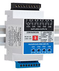
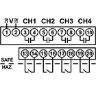
Image may not be exact product—for reference only.
Competitor: ATC Diversified
- Competitor Part #: ISO-24-ACE
- Series: ISO
- Macromatic Equivalent: ISDUR4
- Differences: The ATC Diversified product is panel mounted and accepts 24 VAC input voltage. The Macromatic product installs on DIN-rail or panel mounts with 2 #8 screws and accepts 102-132 VAC & 10-125 VDC input voltage.
- Family: INTRINSICALLY SAFE RELAY
- Function: 4 CHANNEL - Selected operating configuration applied to all channels
- Input Voltage: 102-132V AC & 10-125V DC
- Output: 5A SPST-NO
Description of function:
Each ISD Series product consists of 4 intrinsically safe inputs and 4 corresponding electromechanical relay outputs. With input voltage applied, the V LED will be ON (GREEN) to indicate power is applied. When the input device is closed, the input LED is ON (GREEN). When the output relay is energized, the output LED is ON (ORANGE).
These products offer four operating configurations which are user selectable and easily accessible.
ISDUR4 has a two-position DIP-switch that enables the selection of configurations that apply to all channels.
Configurations applied:
Standard Logic (DIP Switch set to “STD”):
When the input device in the hazardous area is closed, the corresponding output relay is energized. When the input device opens, the corresponding output relay will de-energize.
Inverse Logic (DIP Switch set to “INV”):
When the input device in the hazardous area is open, the corresponding output relay is energized. When the input device closes, the corresponding output relay will de-energize.
No Time Delay (DIP Switch set to “0 S”):
The output relay will have an immediate change in status in response to the input device closing or opening.
Fixed 2 Second Delay (DIP Switch set to “2 S”):
The output relay will delay 2 seconds before a change of status in response to the input device closing or opening.
Application Information
- Voltage Tolerance: 102-132V AC (50/60Hz.) & 10-125V DC
- Load (Burden): 5VA Maximum
- Response Times: Standard (DIP Switch set to "0S"): < 50ms; Delay (DIP Switch set to "2S"): Fixed 2 Seconds
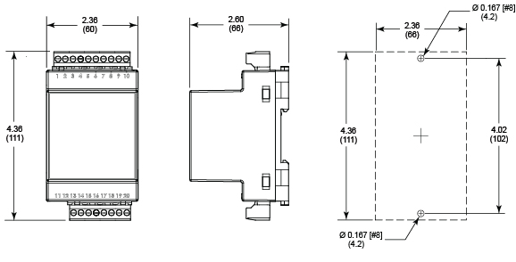
- Mounting: Mounts on 35mm DIN-rail or panel-mounted with two #8 screws when DIN-rail clips are fully extended from under the enclosure.
- Indicator LED: V: ON (Green); Inputs: ON (Green); Outputs: ON (Orange)
- Output Contacts: SPST-NO (Form A) 3A Resistive @ 125V AC @ 60oC & 30V DC Resistive; 5A Resistive @ 125V AC @ 40oC & 30V DC Resistive; Pilot Duty Rating D300
- Life: Electrical: 50,000 Closures @ Full Load AC ; Mechanical: 5 Million Closures @ No Load
- Temperature: -28o to 60o C (-18o to 140o F)
- Approvals:


Dimensions
Inches (Millimeters)